The Situation at hand
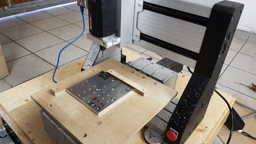
For quite some time now, we had an ISEL EP1090 standing at home, unused. Having a CNC-machine this close opens many possibilities, but in the current state of the machine, it´s possibilities were limited, due to:
- It is just 2.5D (Not bad, but real 3D would have been nice)
- Acceleration and deceleration were catastrophic. Although I can´t say it for sure, it sounded like every movement started with maximum speed and ended with an abrupt halt.
- No probing. Every time I used the ISEL I used a precision paper in order to lover the drill bit onto the workpiece, till I could feel a light drag on the paper
- Finally: The control software. It was ridiculously hard finding a piece of software, which could communicate with the ISEL (due to a proprietary protocoll) and the ones I found were pretty old and outdated.
The Plan
The original plan was to swap the main processor with an Arduino UNO running grbl. This turned out to be a bad idea. I managed to cram a bareduino into the ISEL but had tons of problems with electrical interference. So, I decided to route the signal cables (for STEP, DIR and the endstops) outside and only let the power electronics, responsible for controlling the motors in the machine base. But first I had to do some digging.
Reverse engineering the circuit board
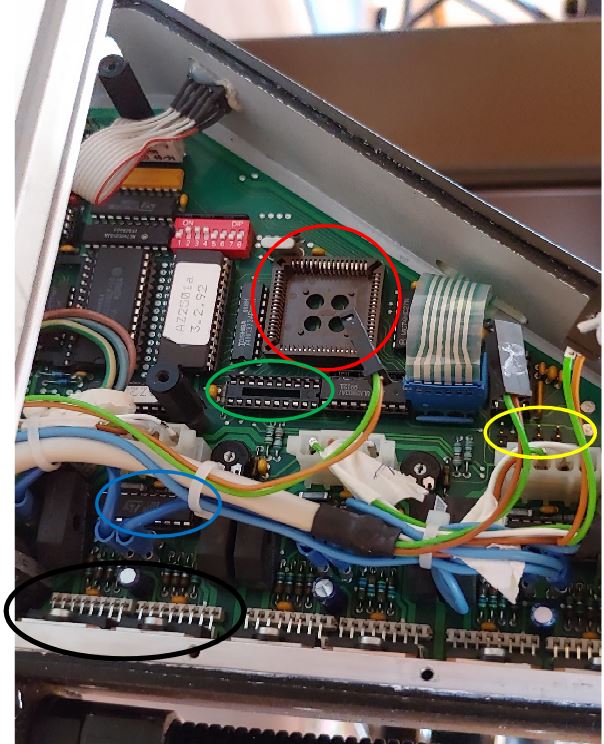
The picture below shows the circuit board of the ISEL. In the red circle you can see the socket of the old processor. I removed it, so that it doesn’t interfere with our new brain. The unpopulated socket next to it (green circle) is home to the MC74HC245A. This is a transceiver chip, used to pass the signals from the processor to the driver IC of the stepper motor control. We will use this socket to communicate with the stepper motor control und repurpose the original chip (Although it should also work without it).
Additional info:
- Blue circle: The L297 stepper controller. This chip converts the DIR and STEP signals into signals usable by a motor. It supports Full and Halfstep mode.
- Black circle: The L298N motor driver. For each motor two chips are used in order to increase the maximum output power
- Yellow circle: I know, it is a little bit hard to see, but this is the place where the connectors for the endstops originally were plugged in.
- The molex connectors are running from the board to the motors. It starts with the motor for the z-axis at the top. The middle connector is for Y (left, right) and the one on the bottom for the x-axis (front, back)
The actual conversion
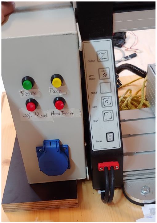
The new brain of the ISEL will be an Arduino Nano, sitting on a PCB by the Arduinoclub. This PCB does all the work of isolating the inputs and outputs and routing all the pins to screw terminals for easy access. Initially we had created our own Arduino board, which would still fit inside the original casting, but due to electrical interference problems, we decided to use this solution.
The PCB is mounted in a control box, wiring is done according to the following plan: https://www.arduinoclub.de/wp-content/uploads/2019/01/EN_AC-CNC2018-N-GRBL_R2.x_Schema.pdf
There are only a few things to be noted, which we changed:
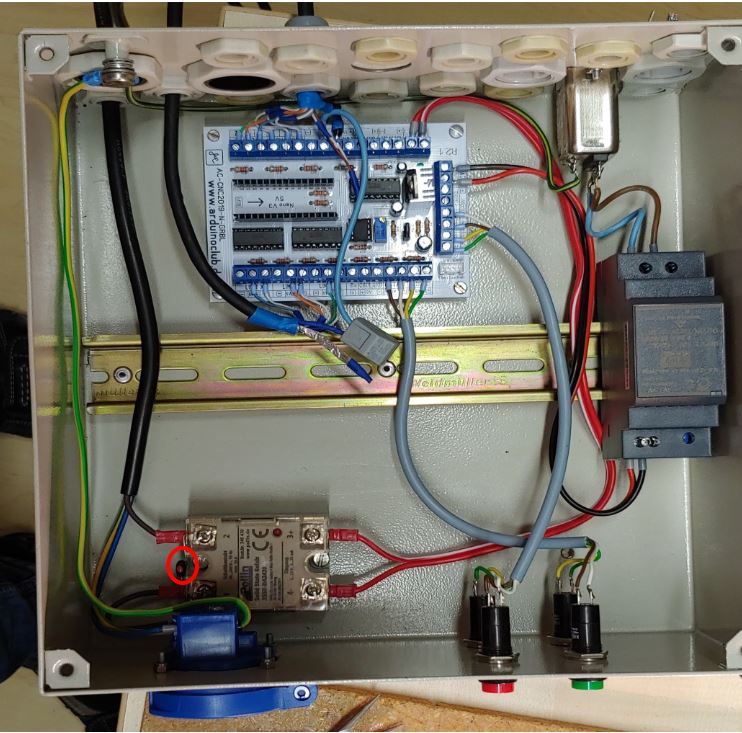
- We added a filter in front of the 12V power supply, which is sitting on the rail
- On the output side of the solid state relay a varistor was added, following the connection diagram in the datasheet of the relay. (red circle)
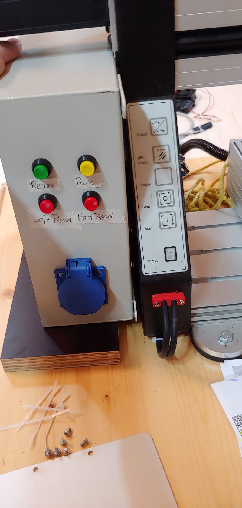
- The relay is used to switch the socket located at the front of the control box, which is used to power up the spindle. Always have an electrician do the high voltage work!!!
- We used a CAT 7 LAN cable to bring the signals from the PCB to the inside of the ISEL, because it has good shielding. Due to the signals being digital, the shielding is grounded on both sides of the cable
We run the two CAT7 LAN cables through the old serial port, in order to avoid drilling holes into the body of the ISEL. We 3D printed a small adapter, which can be screwed into place. This is the red piece, shown below. On the inside, one cable tie on each cable makes sure, that the cable won´t slip out. If you want to replicate this, remember to pull the cables through the red adapter before you start to solder pins to the cables.
Get the signals to the ISEL
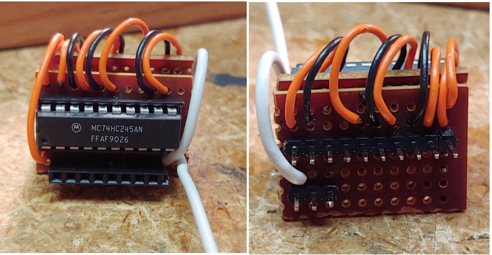
This took quite some time, till we found a solution, which could be easily reverse in case something went wrong. As mentioned in the beginning, we will be using the socket of the MC74HC245A in order to interfere with the power electronics. Luckily for us, normal headers fit perfectly inside the socket, so we made the following board.
We have 2 PCBs connected back to back. On the underside we have the pins, which go into the socket, where the MC74HC245A once was located on the ISEL board. Till now we have had no problems with it coming lose. The top side reuses the MC74HC245A in order to bring the signals to the Stepper motor drivers. You don´t have to use this chip, because in theory the output of the Arduinoclub-PCB should be sufficient, but we wanted to be safe.
Let’s start with the left side:
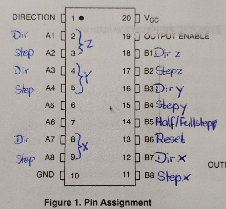
- The direction pin is connected to VCC. The MC74HC245A can be used in both directions and normally you could switch those. This isn´t needed here, so we keep it just the way we need it.
- After that the pins for the Z, Y and X axis are routed out to the header. As you can see A5 and A6 aren´t connected. I will explain why, when we come to the right side.
- GND is obvious. The only thing to note is the white cable running out in Figure 6. This is used as ground for the shielding of the cables running from the cable cabinet to the ISEL.
And the right side (output side):
- The OUTPUT ENABLE pin is also connected to VCC. Otherwise the output wouldn´t work.
- Now we have the same configuration as on the left side. Just two pins are labelled here:
- B5 – Half/Full step: The motor driver of the ISEL allows half and full step mode. Originally you could set this with a small DIP switch on the ISEL mainboard, but this switch is running to the processor and as we didn´t have the option to make an adapter fitting it´s socket, we decided on using the half-step mode from now on.
- B6 – Reset: This pin must be pulled to high, because otherwise the motordrivers won´t work
- -> As we have no intention of changing the state of those pins, we used two 13k pullup resistors
Links
You can find the whole project with even more pictures and the settings for grbl on github:
https://github.com/Sebastian-Schuetz/ISEL-EP1090
Bonus Picture
The initial brain swap showed everything neatly packed away in the side, but the interference made the Arduino restart every time we started the the spindle. As one could guess, this makes the a CNC-machine pretty useless…