Introduction
As some propably know, I am working on an exoskeleton for the lower limbs. And as it would have it, I needed a precise, fast and cheap (!) way to meassure a distance as part of my design. Sadly it seems, as if most of the time you only are able to choose two of the three.
So, I figured, this must be a solveable problem and if I am willing to design the part myself I will propably get it way cheaper. So off I went … looking at what options are available to meassure a small distance (~ 5 cm) in the hobby electronics/semi professional world.
| Option | Notes |
|---|---|
| Hall Effect Sonsors | Meassure the strength of a magnetic field; no touch measurment; cheap |
| Linear potentiometer | cheap; varying accuracy; not to happy about vibrations |
| Laser | eather Time of flight or triangulation; not so cheap; sometimes difficult for short range applications |
| Ultra sound | cheap; not so precise |
| Magnetic Tape Encoders | definitly not cheap; very precise; did I mention expensive |
| Linear Encoders | same as with magnetic tape |
After looking at my options I decided that a Hall Effect Sensor was the way to go and started to look for data sheets.
Design
At first I figured, I take one hall effect sensor and have a magnet in front of it, but soon I stumbled across these great application notes from Texas Instruments:
- Linear Hall Effect Sensor Array Design (Application Note)
- Calibration of Hall Effect Sensors (Application Note)
- Tracking Slide By Displacement (Application Note)
Basically describing exactly what I was looking for. After some thinking I went with the DRV5057 with PWM (DRV5057 data sheet) output, as it would safe me the hassle of dealing with a ADC and most of the time is more precise than its analog counterpart.
With this out of the way, I set out to design my first ever PCB using the open source software KiCad. For version 1 I went with the most simple design I could imagine. A double sided board with a simple pin header, four DRV5057 and the corresponding passiv components on it.
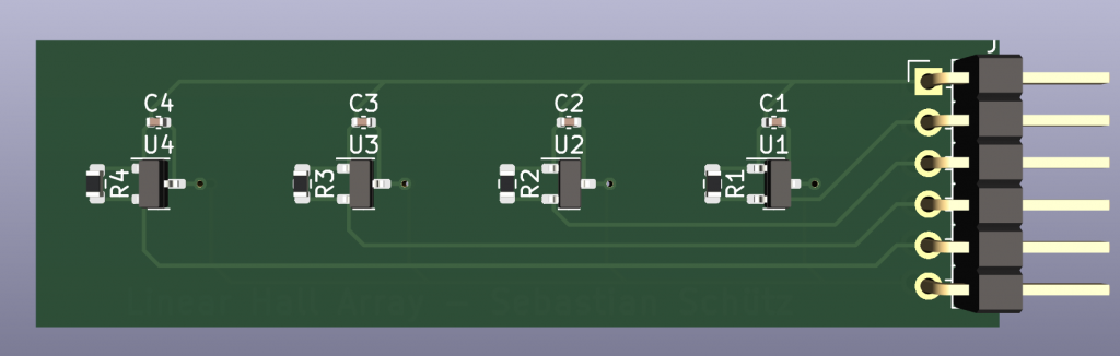
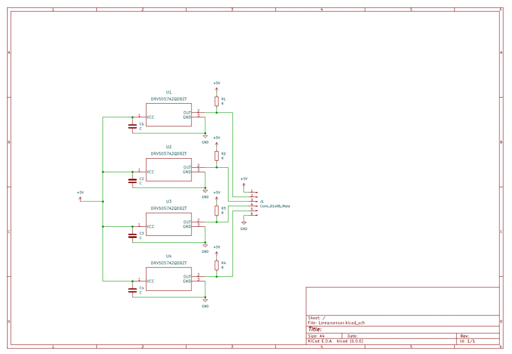
I knew, that this should work, as it is a fairly easy board, but I figured it is always great to get feedback and thanks to the nice people of r/PrintedCircuitBoard (Link to reddit post) I also got a lot of good feedback, which will be incorporated in version 2. Especially:
- Adding a power on LED
- Mounting holes
- smaller header (2×3), allowing for a smaller footprint
- Ferrit beads (propably overkill, as we are dealing with only 2 kHz, but it never hurts)
- Diode to protect against reverse polarity
- Better routing of the paths
But those updates have to wait for a lazy saturday.
To be continued…
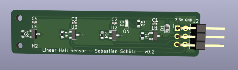
And this day came. Apart from the ferrit beads I added all the improvements. Somehow I screwd up with the footprint of the protective diode during the ordering process…
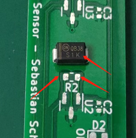
Yeah, one should realy double check your footprints!
But in the end the diode is non-critical so I kicked it out and recieved those gorgeous boards in the mail.
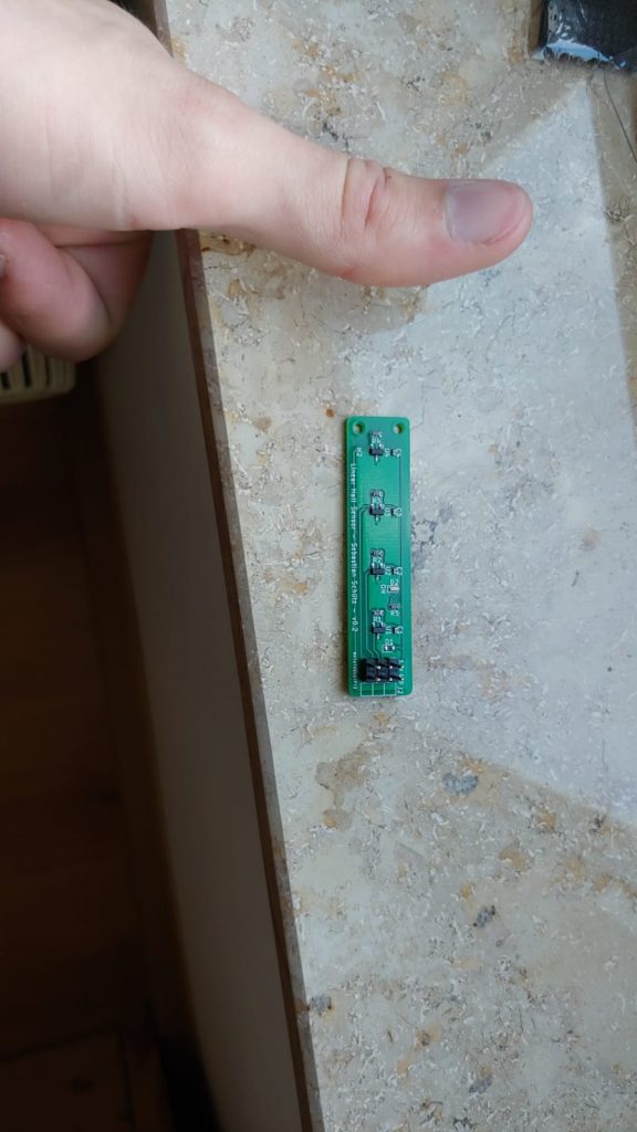
Don´t look at the header. Someone forgot to specify for 90° male header pins…
So, what is next? Next up will be printing a housing for those sweet PCBs and writing some software for calibration. I have something in mind with the ISEL and double checking the accuracy, but we will cross that bridge, when we get there.
If you want to use the design or improve on it, feel free to check it out on Github!
https://github.com/Sebastian-Schuetz/Linear-Haff-Effect-Sensor-Array/